How to Use a Regulator to Reduce Time Delay in an Analytical Instrumentation System
How to Use a Regulator to Reduce Time Delay in an Analytical System
Mike Strobel, Field Engineering Supervisor
Process measurements are instantaneous, but analyzer responses never are. From the tap to the analyzer, there is always a time delay. Unfortunately, this delay is often underestimated or misunderstood.
In analytical sampling systems, time delay is defined as the amount of time it takes for a new sample to reach the analyzer. A separate blog article explains how time delay works and tips to minimize it at a high level, but in this piece, we’ll focus on how to control time delay with a pressure regulator. Regulators control pressure, and pressure in an analytical system is closely related to time. In the case of gas systems with a controlled flow rate, the lower the pressure, the shorter the time delay.
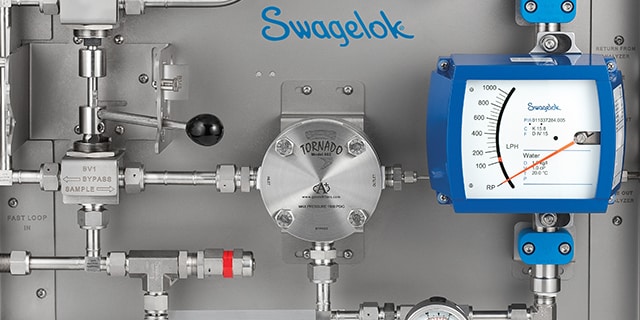
Time delay may occur in any of the major parts of an analytical instrumentation system, including the process line, tap and probe, field station, transport line, sample conditioning system, stream switching system, and analyzer. The diagram below is an example of a typical process analyzer sampling system.

Time delay is cumulative. It consists of the total amount of time it takes for fluid to travel from the process being monitored to the analyzer. You can learn more about how to measure time delay here. For now, we will focus on the field station and the important role a regulator plays in reducing time delay there.
 Before the Field Station
Minimizing time delay begins with the location of the tap. It is best to locate the tap as close to the process analyzer as possible, but also upstream of sources of process time delay, such as drums, tanks, deadlegs, stagnant lines, and redundant or obsolete equipment.
When sampling a liquid, pressure at the tap should be sufficient to deliver the sample through the transport lines or fast loop without a pump—an expensive component that introduces additional performance variables.
In many cases, you may not be able to dictate the location of the tap. You may have to make do with an existing tap location, and often, an existing analyzer shed location as well. If the tap is a long distance from the analyzer, a fast loop is recommended as a means of quickly delivering fluid to the analyzer and returning the unused portion to the process.
In most analytical instrumentation systems, another source of time delay is the probe. The larger the probe’s volume, the greater the delay. Volume will be affected both by the length and width of the probe. When attempting to minimize time delay, choose a low-volume probe.
 At the Field Station
In cases where the process analyzer requires a liquid sample, a regulator in the field station is not used. It is better to keep liquids at high pressure to avoid the formation of bubbles. In the case of a gas sample, a field station is used as a means of reducing pressure in the transport lines.
Time delay decreases in direct proportion to absolute pressure. At half the pressure, you will get half the time delay. The field station is located as close to the tap as possible. The sooner the pressure is dropped, the better. Let’s look at three possible applications for a regulator in a field station. With each, the regulator is configured somewhat differently.
 Regulator Application #1
In the first application, the objective is to reduce gas pressure. The pressure drop is not expected to produce condensation. Therefore, a simple pressure-reducing regulator may be used. A pressure-reducing regulator maintains constant pressure at the outlet. A sensing element, typically a diaphragm or piston, moves in response to downstream pressure, allowing the control element, most often a cone-shaped poppet, to change the flow area of the orifice through which the gas passes. As the sensing element is pushed up in response to higher pressure, the control element moves closer to the regulator seat and the orifice area becomes smaller. As the sensing element moves downward with lower pressure, the orifice becomes larger. In most analytical regulators, a handle on the regulator allows the operator to set the outlet pressure by compressing or relaxing a set spring which drives the movements of the sensing element against the outlet pressure.

A metal diaphragm is ideal in applications where the inlet pressure does not vary sharply or where chemical compatibility is important. However, in applications where the pressure may be inconsistent or spike, a piston-style regulator may be more appropriate.
 Regulator Application #2
In our second regulator application, the pressure drop is expected to cause condensation. With a drop in pressure, almost all gases lose energy, known as the Joule-Thomson effect—resulting in cooling. If the gas is close to its dew point, this cooling could cause condensation. In some cases, the loss of heat may be great enough to cause the condensation, thus potentially freezing up the regulator. Because of the Joule-Thomson effect, a heated regulator may be required to keep the temperature of the gas above the dew point. A heated regulator is a pressure-reducing regulator in which the system fluid flows over a heated element. A heater cartridge is required.
You can calculate the amount of energy (or wattage) required from the heater cartridge so that you can specify one in the correct power range. Every gas has a Joule-Thomson coefficient, which is plugged into a formula along with the pressure drop and flow rate to produce the number of watts required.

 Regulator Application #3
In our third regulator application, a liquid must become a gas before it can be analyzed by a gas chromatograph or other analyzer. In this case, a vaporizing regulator is used. Vaporizing regulators can be challenging to select but can be a reliable means of preparing a liquid sample if properly sized and installed. The objective of a vaporizing regulator is to instantly flash the entire sample into a gas to ensure the vaporized sample is representative of the liquid process.
With vaporizing regulators, one must pay close attention to temperature and vapor flow rate. If the flow is too great, the sample will be only partially vaporized, and liquids will flow through the regulator and toward the analyzer. If the vaporizer temperature is too high, the liquid sample upstream will be vaporized. You can learn more about managing vaporization in sampling systems here.
Finally, be sure to set up your vaporizing regulator correctly to avoid creating considerable time delay. As the fluid changes from liquid to gas, volume will increase dramatically. The amount of increase will depend on the liquid’s molecular weight. Typically, the measured vapor flow after the regulator will be >300 times the liquid flow before the vaporizing regulator.
For example, with a vapor flow of 600 cm3/min., liquid flow may be less than 2 cm3/min. In this case, the liquid will take 25 minutes to travel through 3 meters (approximately 10 feet) of 6 mm (1/4 in.) tubing. To reduce this time, we must reduce the volume of the tubing preceding the regulator. For example, with only 30.5 cm (1 ft.) of 3.2 mm (1/8 in.) tubing, it would take only 30 seconds for the liquid to reach the regulator. To this time, however, we must add time delay in the probe. The narrower the probe, the faster the response.
Another means of attaining a faster response is to move the vaporizer closer to the analyzer with the aid of a liquid fast loop. In the diagram below, the regulator is located after the fast loop filter with a second liquid slow bypass loop ensuring that good liquid flow continues right up to the vaporizing regulator. The objective is to minimize slow-moving liquid volume going to a vaporizing regulator.
 Make the Right Regulator Choices to Diminish Delay
A regulator is a critical tool in addressing time delay in an analytical system. The lower the pressure in a gas system, the faster the response time. In general, the sooner the pressure can be dropped in a gas system, the better. In cases where a liquid is being vaporized, consider a liquid fast loop to keep the liquid moving right up to the vaporizing regulator. The field station is one place in a complex analytical instrumentation system where time delay can be significantly reduced, but the approach to time delay must always be comprehensive. To reduce time delay, all potential causes of delay in the system must be scrutinized.
If you are struggling with time delay in your analytical systems, beyond following the advice above regarding regulator selection, there are several other places you can turn for help. We offer several sampling system training courses taught by sampling experts, we offer pre-engineered analytical subsystems designed according to best practices, and our field engineering team can also come on site to help you identify and troubleshoot problems with your analytical systems. To learn more or to start a conversation about reducing delay in your analytical system, click the button below.
Related Articles
4 Areas to Inspect When Measuring Time Delay in Sampling Systems
In a process analyzer sampling system, there is always a time delay before you obtain a reading. However, underestimating this time delay can lead to inferior process control. Learn which four areas you should closely inspect to diminish time delays.
Why Haven’t Sampling Systems Improved — Three Main Reasons
The past 50 years, process analyzers have vastly improved— but sampling systems have not. Luckily, most issues are due to human error & can be corrected with proper training. Learn three reasons why sampling systems fail & solutions for your plant.
Understanding and Measuring Time Delay in an Analytical Instrumentation System
Process measurements are instantaneous, but analyzer responses are not. Time delay in sampling systems is the most common cause of inaccurate results from process analyzers. Learn how to understand and reduce time delay in your analytical systems.