4 Areas to Inspect When Measuring Time Delay in Sampling Systems
4 Areas to Inspect When Measuring Time Delay in Sampling Systems
In a process analyzer sampling system, there is always a delay between the moment you grab the sample and the time you obtain a reading.
Time delay is cumulative, accounting for the total amount of time it takes for a sample to travel from the tap in the process line to the process analyzer—where results are obtained. This time delay may be longer than you think and underestimating it can lead to inferior process control. If you are assuming your time delay is equal to one minute, but it’s actually two hours, your analyzer readings may no longer be relevant or purposeful. You want to minimize this delay, with a common goal of one minute or less from the tap to the analyzer reading.
You’ll find causes of time delay throughout your entire analytical instrumentation system. Here are four main areas to examine to begin reducing your system’s time delay:
- Delay in the probe
- Delay in sample transport (including the field station and transport lines)
- Delay in sampling conditioning (including stream switching)
- Delay in the analyzer

1. Time Delay in the Probe
Avoid overly large sample probes. The probe should be long enough to reach to the middle third of the process line diameter, where the stream moves the fastest and provides the cleanest, most representative sample. It should not be any longer – or wider – than necessary, because the larger the probe’s volume, the greater the delay.
Tap location in the process tube is another related issue to consider. If you locate the probe near a low-flow section of the process tube, you will need to wait longer for any change in the process chemicals to show up. For example, new molecules entering a large-volume tank or drum will create a ‘mixing volume,’ with both new and old molecules showing up at the exit until the volume is fully purged. To reduce time delay, you should not locate the tap downstream of a mixing volume. Instead, position the tap upstream of such sources of in-process time delay, including drums, tanks, dead legs and stagnant lines.
2. Time Delay in Sample Transport
- Remote Sample Tap Locations: The further a sample has to travel for analysis, the longer the time delay. Locate the tap as close to the analyzer as possible. For longer transport lines, consider using a fast loop to accelerate flow and provide your analyzer with a more recent sample.
- Line Length and Diameter: The further the sample has to move and the larger the internal volume of the transport lines, the longer the time delay. To reduce this delay, calculate and adjust the line length and diameter accordingly to ensure accuracy.
- Low Pressure in a Liquid Sample Transport Line: For liquid samples, the tap location should provide enough pressure to deliver the sample through the transport lines or fast loop without a pump. Avoid adding costly extra variables, such as a pump, as they increase time delay.
- High Pressure in a Gas Sample Transport Line: With a gas, the higher the pressure, the slower the flow. To speed up flow – and therefore reduce time delay – lower the pressure. For example, at half the pressure, you will get half the time delay.
3. Time Delay in Sample Conditioning Systems

- Unpurged Tee-pieces Causing Dead Legs: A dead leg is an unpurged side volume that allows molecules to diffuse in and out of the flowing system media. Any tee or cross in the analyzed sample line is a dead leg unless all its ports are flowing. Common dead legs include connection points for pressure and temperature gauges, purge and bleed valves, calibration manifolds, and lab sampling points. You will need to purge these areas before performing sample analyses, because the purging period contributes to time delay. Relocating the dead leg (such as a gauge) is sometimes the simplest solution.
- Adsorption of Samples on Tube Walls and Filters: When a sample touches the walls of tubing or any other solid surface, a few of its molecules stick to that surface. In a parts-per-million (ppm) analysis, the loss of molecules due to adsorption (or gain from desorption) can be significant. The loss is only statistically significant, however, with gas samples. Worry about adsorption with a liquid sample only when you’re measuring less than 1 ppm. For gas samples, build in sufficient wait times between switching sources to allow for the previous gas molecules to clear.
- High Internal Component Volumes: To ensure a representative sample – and obtain accurate analyzer readings – the entire volume of every device in the flow path must be purged. If you have a large volume device, such as a filter or coalescer, allow enough time to purge it thoroughly. A general guide would be to flush the device with three times its volume. Minimize the size of these components when possible.
4. Time Delay in the Analyzer
- Discontinuous Analyzer Response Times: Certain analyzers take more time than others to perform their analyses due to processes that take place within the analyzer. For example, a colorimeter needs to develop its measured color before completing an analysis, and a gas chromatograph needs to separate its measured components before analyzing them.
- Continuous Analyzer Response Times: Some analyzers run continuously, but even these do not provide an immediate result, so there is always some delay.
- Manual System Operator Response Times: When manually managing the sample analysis process, be sure to factor in the inevitable time delay that occurs before the operator notices and responds to necessary system adjustments.
Know Your Time Delay to Enable Accurate System Responses
It’s important to recognize how much time has passed between the moment when the sample is first taken from the process line at the tap, to when the sample reaches the analyzer to when you receive your result. A wrong assumption about this time lapse means that you do not understand the relationship between what’s in the process line and the analytical result. Understanding the elements of your sampling system susceptible to delay discussed with this article (probe, sample transport, sample conditioning, and analyzer) will lead to conclusions regarding where time delay is occurring within your system and improve overall process control.
Related Articles
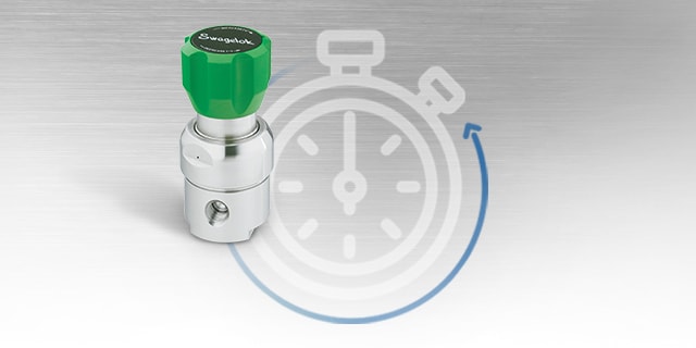
How to Use a Regulator to Reduce Time Delay in an Analytical Instrumentation System
Time delay is often underestimated or misunderstood in analytical systems. One way to mitigate this delay is with a pressure-controlled regulator. Learn how manage your analytical system’s time delay with tips from the experts at Swagelok.
Understanding and Measuring Time Delay in an Analytical Instrumentation System
Process measurements are instantaneous, but analyzer responses are not. Time delay in sampling systems is the most common cause of inaccurate results from process analyzers. Learn how to understand and reduce time delay in your analytical systems.
Why Haven’t Sampling Systems Improved — Three Main Reasons
The past 50 years, process analyzers have vastly improved— but sampling systems have not. Luckily, most issues are due to human error & can be corrected with proper training. Learn three reasons why sampling systems fail & solutions for your plant.