How to Manage Supply Pressure Effect (SPE) in Pressure-Reducing Regulators Used to Maintain Gas Pressure Control in Industrial Gas Systems
How to Manage Supply Pressure Effect (SPE) in Pressure-Reducing Regulators Used in Industrial Gas Systems
Wouter Pronk, Senior Field Engineer, Swagelok
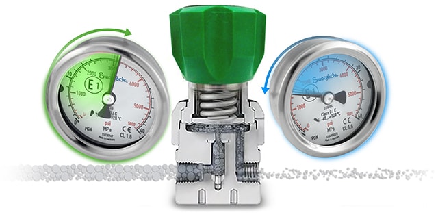
Fluid system operators running a process line from a gas cylinder source may occasionally observe the phenomenon of outlet pressure increasing in a pressure-reducing regulator for no apparent reason. As the cylinder empties, the inlet pressure to the regulator decreases. Many skilled technicians would expect the outlet pressure to decrease concurrently, but instead, the outlet pressure rises. This occurrence is known as supply pressure effect (SPE).
What is Supply Pressure Effect (SPE)?
Supply pressure effect, also referred to as inlet dependency, is defined as the change in outlet pressure due to a change in inlet, or supply, pressure. Under this phenomenon, inlet and outlet pressure changes are inversely proportional to each other. If the inlet pressure decreases, there will be a corresponding outlet pressure increase. Conversely, if the inlet pressure increases, the outlet pressure decreases.
A regulator’s SPE is typically provided by the manufacturer. SPE is usually depicted as a ratio or percentage describing the change in outlet pressure per change in inlet pressure. For example, if a regulator is described as having a 1:100 or 1% SPE, for every 100 psi drop in inlet pressure, the outlet pressure will increase by 1 psi. The degree of outlet pressure variation for a regulator can be estimated with the following formula:

Unbalanced vs. Balanced Poppet Design in Spring-Loaded Regulators
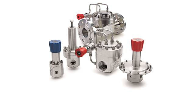
One of the most common types of regulators is a spring-loaded pressure-reducing regulator. A spring applies force on a sensing element, either a diaphragm or a piston, which controls the poppet over the orifice—therefore controlling the outlet pressure.
In an unbalanced poppet design, the inlet pressure pushes up on the poppet and applies pressure to a portion of the poppet equal to the seat area. As a result, any decrease in inlet pressure means less force is pushing up on to the poppet, allowing the strong set spring to push the poppet slightly further from the seat—thus increasing the outlet pressure. This resulting rise in outlet pressure is not strong enough to fully counterbalance the set spring force to close the poppet to its original position. The outcome is an increase in outlet pressure due to SPE.
Because regulators operate on a balance of forces, the amount of SPE can be determined by the ratio of areas on which pressures acts on the poppet and sensing areas. That is to say that regulators with large sensing areas and small poppets will have the lowest SPE and those with small sensing areas and large poppets will have the highest SPE.
To demonstrate the effect of an unbalanced poppet design on SPE, gradually decrease the inlet pressure. At an inlet pressure of 1160 psig (80 bar), the outlet pressure is 43.5 psig (3 bar). But when inlet pressure is decreased to 870 psig (60 bar), the outlet pressure jumps to 53.7 psig (3.7 bar). Since the inlet pressure acts on the entire surface of an unbalanced poppet, any change in inlet pressure produces a large change in force, driving a bigger shift in the balance of forces within the regulator.

A common method for reducing supply pressure effect, especially within higher-flow applications where poppets are generally larger, is to use a regulator with a balanced poppet design. The intention of this regulator design is to minimize the area on which the high inlet pressure can act. This is accomplished by allowing the lower outlet pressure to reach a portion of the underside of the poppet through an orifice that runs vertically along the poppet and sealed by an O-ring around the lower stem of the poppet. In terms of SPE, any change in inlet pressure will result in a smaller change in force because the pressure is acting on a much smaller area.
To demonstrate how SPE impacts a balanced poppet regulator, envision gradually decreasing the inlet pressure as demonstrated previously with the unbalanced poppet design. Just as before, at an inlet pressure of 1160 psig (80 bar), the outlet pressure is 43.5 psig (3 bar). However, when inlet pressure is decreased to 870 psig (60 bar), the outlet pressure only increases to 46.4 psig (3.2 bar). In fact, even at an inlet pressure of 725 psig (50 bar), the outlet pressure continues to hold steady at 46.4 psig (3.2 bar).

Notice how the effect on the outlet pressure with a balanced poppet regulator is lessened from the previous regulator arrangement. An additional benefit of balanced poppet regulators is their ability to reduce lockup—the tendency for the poppet to snap shut as downstream flow decreases to zero. Excessive lockup is undesirable because it can cause a spike in outlet pressure as the poppet rapidly closes. Still, SPE will always be present in regulators used in gas systems, regardless of poppet design. Even if a poppet/valve is closed very slowly, whether in a dynamic or static process with flow or no flow, SPE will occur. After the change of an empty cylinder for a full one, the set outlet pressure will be different. Informed design decisions can simply help reduce the effect.
Single-Stage vs. Two-Stage Regulation
Two-stage pressure reduction is a good solution for minimizing supply pressure effect in practically any application. This method involves installing two single-stage regulators in a series or combining the regulators into one assembly. A dual-stage regulator—such as a Swagelok® KCY series regulator that conducts two-stage pressure reduction in one body—is a strong option for lower-flow applications such as analytical instrumentation systems. Each regulator controls the inlet pressure variation to a certain degree, but together, the two regulators keep the outlet pressure very close to the original set point.
To calculate the variability of outlet pressure for a two-stage regulator setup, the inlet pressure difference is multiplied by the SPE of each regulator. This is illustrated in the following equation:

Keep in mind that SPE is an inverse relationship between inlet and outlet pressure variables. The first-stage regulator will encounter an increase in outlet pressure as the gas cylinder empties and inlet pressure decreases. This increase will be fed into the second stage and result in a succeeding decrease on the outlet side of the second-stage regulator. Because the first-stage regulator experiences the large inlet change and outputs a smaller outlet change, the second-stage regulator reacts only to the small inlet change from the first stage and shows minimal pressure decrease on the outlet side. As soon as the inlet pressure drops below the set pressure of the first stage regulator, the setup will act as a one-stage regulator system.
To demonstrate supply pressure effect, the below example uses a KCY model pressure-reducing regulator. The gas cylinder empties from 2500 psig (172 bar) to 500 psig (34 bar). Assume that each regulator has a 1% SPE. With a 2000 psig (137 bar) inlet pressure drop, the first-stage regulator will experience a 20 psig (1.3 bar) increase in outlet pressure. As a result of that increase, the second-stage regulator will only experience a 0.20 psig (0.01 bar) decrease in outlet pressure. Notice how the effect on the outlet pressure is dramatically lessened from the previous regulator arrangements.

In terms of controlling supply pressure effect, a two-stage regulator setup typically will achieve a better outcome than a single pressure-reducing regulator with a balanced poppet. In an application using one gas cylinder to source multiple operations under the same outlet pressure, either option may be sufficient.
On the other hand, applications that require a gas cylinder to supply multiple operations with different pressures will need to use two single-stage regulators to make a two-stage regulator system. If this is the case, set-up the first-stage regulator near the gas cylinder and the second-stage regulator on each of the process lines or at the point of use. To minimize SPE, systems are often built with a two-stage regulator at the gas supply source and a single-stage regulator at the point of use. This excessive setup amounts to three-stage regulation—which is unnecessary for most applications. Two single-stage regulators in series will yield minimal SPE at a lower cost.
Learn more about single and two-stage pressure regulation:
The Benefits of Engineered Gas Distribution Systems
Another option to manage SPE is to employ a fully assembled and tested gas distribution system composed of modular subsystems designed and configured specifically to meet the needs of your application. In these systems:
- A source inlet module, such as the Swagelok® source inlet (SSI), or source inlet panel establishes a connection between the high-pressure gas source and the distribution system. For a single gas cylinder, the assembly can be as simple as a hose and connector, while multiple cylinders may require a manifold incorporating multiple hoses and valves. These inlets can be highly configurable to purge or vent gases when changing bottles—promoting operator safety—or can be created to vent individual lines to maximize uptime.
- A gas panel, such as the Swagelok® gas panel (SGP), completes the first pressure reduction of the source gas and ensure it is delivered at the correct flow rate to the next stage of the system. This is the part of a gas distribution system where SPE can best be controlled. Pressure reduction is accomplished in either one stage with a single pressure regulator or two stages through a dual pressure regulator arrangement. These gas panels are easy to service, as any part can be detached and the panel never needs to be removed. Using an SGP with a dual-stage regulator is a highly reliable means of reducing SPE.
- An automatic changeover system, such as the Swagelok® Changeover (SCO) subsystem, switches from one gas source to another to ensure uninterrupted supply. Two pressure regulators with set knobs are connected to one another, but control input from separate gas supply sources (consisting of one or more gas cylinders). One regulator is set to a lower pressure than the other, with the one set at the higher pressure initially supplying gas to the shared outlet connection and the one set at the lower pressure supplying gas once the higher-set regulator’s gas supply runs out. By adjusting the set handle 180°, the pressure setting of the two regulators are reversed, allowing empty cylinders to be exchanged while the system continues to operate. Well-designed changeover subsystems will allow you to specify changeover setpoints to reduce wasted gas left in cylinders.
- Finally, a point-of-use system, such as the Swagelok® Point-of-Use (SPU) assembly, provides a final stage of pressure control prior to gas being used. These systems typically include a regulator, a gauge, and an isolation valve and offer a convenient, accurate method of adjusting pressure to meet application needs.

Conclusion
With the regulator controlling outlet pressure from a gas cylinder, supply pressure effect is a phenomenon that will always be present. Whenever there is a change in inlet pressure, there will be a corresponding change in outlet pressure. You can minimize supply pressure effect for many applications by using a single-stage regulator with a balanced poppet design, by using a two-stage regulator, or by using fully configurable gas panels like the ones available through the Swagelok® gas distribution program. If your gas source is servicing multiple operations with different pressure requirements, you may need multiple single-stage regulators—one near the gas source and another on each process line—or you can use preassembled gas distribution subsystems designed to perform effectively in these cases.
Need help selecting the right regulator for your fluid system applications? We can assist you in identify solutions to improve operations based on your unique systems. Gas distribution system advisors are available to evaluate your existing gas distribution systems and identify opportunities for improvement, and associates at your local Swagelok sales and service center can also advise you on component selection. For more information, reach out using the link below.
Related Articles
How to Flatten a Regulator Flow Curve to Reduce Droop
Droop is an issue for every pressure-reducing regulator. Learn how to minimize droop and flatten regulator flow curves with various dome loaded regulator configurations explained by Jon Kestner.
Cut Maintenance Costs with Enhanced Gas Panels
Learn how easy-to-use gas panels and an overall more efficient gas distribution and delivery system can help laboratories, refineries, and other facilities drive down maintenance costs.
Q&A: How to Optimize Your Gas Distribution System
Learn about common challenges that can hamper the safety and efficiency of important gas distribution systems and how a professional evaluation of those systems can provide long-term value.