Back-Pressure Regulators: How They Work & Tips for Engineers
Back-Pressure Regulator Set Up for Sampling Systems: Engineer Guidance
David Rodriguez, Product Manager
Back-pressure regulators play an important role in maintaining inlet pressure (upstream pressure) and protecting sensitive equipment in sampling systems used in many industrial facilities. To make proper use of a back-pressure regulating valve, however, sampling system engineers must be wary of a few common sampling system design mistakes. These include:
- Overlooking the importance of an upstream flow-restrictive device
- Allowing too much flow through the analyzer
- Placing a pressure-reducing regulator in series with a back-pressure regulator with no flow resistance between the two devices

Core Function and Components of Back-Pressure Regulators

How Does a Back-Pressure Regulator Work?
Unlike pressure-reducing regulators, a back-pressure regulator controls inlet pressure (upstream pressure) and is usually installed at the end of a line. On the other hand, a pressure-reducing regulator controls outlet pressure (downstream pressure) and is usually installed at the beginning of a line. Both types of regulators work to balance out forces resulting from system pressure with the loading force in the spring created when establishing the set pressure.
If this balance is upset due to external pressure increasing or decreasing, the regulator’s valve or poppet will move either closer to or further away from the seat. Depending on the nature of the valve’s movement, this will allow flow to move through the regulator’s orifice more easily or less easily until the regulator re-establishes balance.
What are the main components of a back-pressure regulator?
The regulator maintains constant pressure to the analyzer (Figure 1 - A) by adjusting the amount of flow diverted to a bypass. The flow restrictors (Figure R1 & R2) enable the regulator to properly manage pressure.
Figure 1 shows a typical back-pressure regulator set up for an analytical sampling system. When there is flow which is not being used by the analyzer (Figure 1 A), the regulator’s job is to divert that flow into a bypass. As the source pressure changes, the regulator then also changes the amount of diverted flow to ensure that constant pressure is maintained at the regulator inlet and therefore a consistent flow reaches the analyzer.
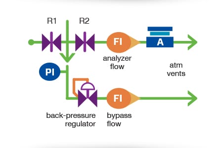
Figure 1. A typical back-pressure regulator setup. Image ©2013 "Industrial Sampling Systems"
A back-pressure regulator requires some flow restriction (typically a needle valve) upstream to help manage inlet pressure (see R1 in figure 1). If there is no restriction between the back-pressure regulator and the system, the back-pressure regulator will open wide in an attempt to move enough gas to drop the upstream pressure. This will not be effective. With a restriction in place, however, the increased flow rate will result in an increased pressure drop over that restriction, helping to drop the pressure downstream.
How can you get calibration or testing services for pressure regulators, gauges, etc.?
Note: Ensuring your back-pressure regulating valve is accurately calibrated is essential for sampling system integrity. Swagelok offers professional evaluation and testing services to help you maintain precise pressure control.
What are common issues with back-pressure regulators?
A common issue encountered by sampling system designers is neglecting to include flow restrictors, assuming the back-pressure regulator alone can manage upstream pressure. Without a restrictor, changes in system flow cause minimal or no change in pressure, leading the regulator to waste process fluid as it tries to increase flow. The controlled inlet pressure remains unchanged, which can result in the regulator staying wide open.
Allowing a lot of flow through the analyzer restrictor (see R2 in figure 1) is another design error because it can cause the inlet pressure of the regulator to drop below its set pressure. This can result in the regulator shutting completely, restricting vent flow. For better control, the upstream flow restrictor (R1) should be sized to allow some flow to go through the regulator even at the maximum analyzer flow rate.
How Do You Set Up a Back-Pressure Regulator?
To set up a functional system like that shown in figure 1, system designers should start by closing R2, adjusting R1 to sufficiently allow bypass flow for the desired analysis response time, and then fine-tuning R2 for the analyzer flow desired. The bypass flow should automatically drop by the same amount. If needed, slowly open R1 until the bypass flow is at least as fast as the analyzer vent flow. This will allow the regulator to control its inlet pressure when the source pressure changes. If you expect that the source pressure will change widely, adjust R1 to generate a small amount of bypass flow at the lowest anticipated source pressure.
With the pressure controlled by the back-pressure regulator in combination with the flow restrictors R1 and R2, we can control the flow to the analyzer and to the vent line.
Since these three components control the flow to the analyzer and the bypass flow, a needle valve or other restrictive device in the bypass vent line is not needed. However, a bypass flowmeter without a needle valve is useful to confirm that the regulator is passing some flow and is controlling its inlet pressure.
How Do You Use Pressure-Reducing and Back-Pressure Regulators in Series?

Figure 2. A pressure-reducing regulator and a back-pressure regulator mounted in series without a flow restrictor. Image ©2013 "Industrial Sampling Systems”
As shown in figure 2, another design error occurs when a back-pressure regulator is placed immediately following a pressure-reducing regulator. Since two regulators cannot control the same pressure – one of them must lose.
To demonstrate this loss, consider two situations. First, if the set point of the back-pressure regulator is higher than the pressure coming into it from the upstream regulator, it will remain closed as there is not sufficient force to lift the back-pressure poppet from the seat and allow flow through the back-pressure regulator. In this scenario, there will be no bypass flow, as the back-pressure regulator will remain closed.
In the second situation, the set point of the back-pressure regulator is lower. Since the flow now increases, the delivery pressure from the pressure reducing regulator will decrease at the rate of the upstream regulator’s droop curve. The flow rate increases drastically, pushing the back-pressure regulator up its accumulation curve and increasing its inlet pressure.
The result of this increase depends on the settings of the two regulators:
- If the two settings are close, the flow rate will rise until the droop pressure out of the first regulator matches the accumulation pressure into the second one. But this results in a very high flow rate.
- If the two settings are further apart, the flow rate will rise until that regulator is no longer in control. One regulator will control the pressure and the other will become a flow restrictor.
What factors affect the performance of a back-pressure regulator?
Choosing the right back-pressure regulator valves involve weighing performance factors like flow stability and material compatibility. Swagelok provides a variety of reliable options specifically for analytical lab sampling systems.

Figure 3.This shows how the system design error in figure 2 causes the two regulators to hold an intermediate pressure between their set points but at a high flow rate. Image ©2013 "Industrial Sampling Systems”
The bypass flow rate depends on the difference between the two set points. It increases until the regulators “declare a truce.” When the upstream pressure changes or flow to the analyzer varies, the two regulators try to hold an intermediate pressure between their set points, but with uncertain results. This is illustrated in figure 3.
This does not mean that the two regulators cannot function in a series, but the only way for this to occur successfully is to have a flow restrictor between them. Figure 4 shows this scenario whereby under the correct settings, both regulators are operating as they should, and the pressure is constant at each end of the two restrictors. The consistency of this pressure allows the flow to be steady and protects the analyzer from variations in source and vent pressure.

Figure 4. This shows how using a flow restrictor between two regulators; a back-pressure, and pressure-reducing regulator, can ensure effective pressure flow and control. Image ©2013 “Industrial Sampling Systems”
Maintaining Back-Pressure Regulators for Reliability
To guarantee the proper functioning of a back-pressure regulator, the sampling system must be designed carefully to make sure that the regulator is doing its job at controlling the pressure. Too high or too low pressure can cause damage or delays in the system.
If you have questions as you are setting up regulators in your sampling systems, we can help. Swagelok field engineers can visit your facilities to evaluate your sampling system, advise on design, or troubleshoot issues. Alternatively, you can learn all about sampling system design and usage through our Process Analyzer Sampling System (PASS) or Sampling System Problem Solving and Maintenance (SSM) training courses.

Related Articles
How to Use a Regulator to Reduce Time Delay in an Analytical Instrumentation System
One way to mitigate time delay is with a pressure-controlled regulator.
How to Flatten a Regulator Flow Curve to Reduce Droop
Consistent pressure control is essential to the safe operation of industrial fluid systems.
How to Troubleshoot Common Regulator Problems
A simple three-step process you can use to troubleshoot issues you may be experiencing with your regulators to help reduce regulator failure.