Sampling Probe, Calibration & Switching Modules to Simplify Sampling
Sample Probe Modules & More Ways to Simplify Sampling with Standard Subsystems
Standard pre-engineered subsystems can bring efficiency to an operation by simplifying the design of fluid sampling and control systems. Using standard systems has the added benefit of significantly reducing installation costs, downtime and overall maintenance, enabling plant and facility managers to acquire and assemble parts while ensuring consistency across facilities—even across continents.
Ultimately, plant and facility managers are saving time, effort and energy that can be repurposed to improve efficiencies and reduce costs in other areas of the plant.
Below are common types of subsystems that can enhance the performance of your sampling systems, and how each can work to improve efficiencies in your sampling system.
Calibration and Switching Modules (CSM)
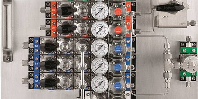
The main function of the CSM is to condition and select process streams, or to select a calibration stream for analysis. At a minimum, each system must have two inlets—two process stream inlets, or one process stream inlet and one calibration stream inlet. The system selects a fluid for analysis in response to a pneumatic pressure signal from an external source, typically the analyzer. The signal opens one of the stream selector valves (SSV) double block-and-bleed valve modules corresponding to the stream containing the fluid to be analyzed. Using a CSM, like the one offered by Swagelok, offers several additional advantages, including:
- A variety of sample conditioning configurations available to meet application requirements.
- A manual calibration option that allows the operator to calibrate the analyzer at any time.
- Color-coded stream identification—process stream inlets will always be blue, calibration streams orange, bypass green and outlet white.
- An integrated flow loop design to ensure consistent delivery times to the analyzer across all streams and eliminate any deadlegs or chance for cross-stream contamination.
- A vented air gap that prevents the hazardous possibility of pneumatic air mixing with system fluid under pressure.
- A modular design that allows for easy maintenance. Individual components can be removed from the assembly by loosening four screws accessible from the top of the panel. There is no risk of accidentally disassembling the whole unit or upsetting other fluid connections.
- A bypass option that allows high flow—and subsequent reduced sample time delay—to the CSM.
Depending on the application, a fast loop module (explained in more detail below) can supply the CSM with flow from a bypass fast loop filter for improved response time to the analyzer. The CSM can incorporate additional bypasses that can be returned to the process line—through the fast loop or separately—or sent to a disposal system. The number of inlets will be determined by the number of samples and calibration lines being sent to a single analyzer.
Sample Probe Modules (SPM)
Using sample probe modules in conjunction with sample probe valves (SPV) can improve safety as well as sample purity and timeliness. A probe provides a faster analyzer response by reducing the volume of the sample system. The nozzle volume can be significant, increasing the required purge volume of the entire sample system. Also, the probe allows the sample to be extracted from the center of the process pipe, which eliminates the extraction of sludge along the pipe walls. Further, using 45° angle cuts from the probe greatly reduces the amount of particulate extracted into the sample system. Both features help ensure the probe extracts a representative sample from the process.
For these reasons, it is recommended to use a probe in pipes larger than 2 in. (50 mm). This is especially critical for pipes larger than 4 in. (100 mm). Probe designs can vary in length, diameter, wall thickness and materials of construction. These parameters will affect the probe’s strength, filtering ability and internal flow velocity. Thicker, larger welded probes will withstand more impact from high process flows but offer slower flow speeds through the larger internal diameter. However, this slower flow speed allows more particles to fall out of the probe instead of continuing into the sample system. Smaller retractable probes are not as strong as welded probes, but their smaller internal volume provides faster flow speeds to the analyzer. Learn more about Swagelok Sample Probe Modules here.
Fast Loop Modules (FLM)
Fast loop modules are designed to handle high flows in sample transport lines to reduce time delays for online analyzer systems. Located at the analyzer shelter and offering a bypass, the fast loop module (FLM) can isolate the sample system and introduce a purge gas for system cleaning. The FLM from Swagelok extracts a sample through a filter while using the high flow rate of the bypass to keep the filter element clean.
A fast loop needs two process taps: one for sample supply and one for sample return. To avoid the cost of a sample pump and improve sampling system reliability, select a return point location that has lower pressure than the supply tap. Choose process tap locations that are as close to the analyzer as possible. If the sample contains a condensable gas, heat the fast loop lines and the FLM above the dew point temperature of the sample at process pressure. A liquid sample will only need to be heated if it is necessary to keep from freezing.
Field Station Modules (FSM)
A field station module (FSM) reduces process gas pressure before transporting it to an analyzer. Transporting a gas sample at low pressure offers three major benefits:
- Faster analyzer response time: In a high-pressure line with downstream flow control, gas molecules are more densely populated which creates slower flow velocity and longer purge times. Lowering the pressure of a gas sample means fewer molecules in the sample transport line and sample conditioning components; therefore, it is easier to flush the system, and the analyzer can respond faster to process changes. The amount of gas held in the transport line is proportional to its absolute pressure. At half the absolute pressure, there are half as many gas molecules in the line, so—all other things being equal—it takes half the time for a fresh sample to reach the analyzer. Typically, an FSM is used when process pressure is 3 bar (gauge) (43.5 psig) or higher.
- Less condensation: The relative humidity of a gas is directly proportional to the partial pressure of water vapor in the mixture. A relative humidity (or saturation) of 100% represents the maximum partial pressure of water vapor possible at a working temperature. Therefore, if water vapor in any gas mixture reaches 100% of its saturation limit, water vapor will begin to condense in a sample transport line. To avoid condensation in gas sampling, the FSM reduces the partial pressure of every gas in the sample mixture. One way to lower partial pressure of every gas is to reduce overall system pressure; the partial pressure of each gas drops in proportion to the overall pressure change. For example, if the absolute pressure of a sample is cut in half, the partial pressure of each gas in the mixture is cut in half as well, which results in half the water saturation in the sample. Using an FSM significantly reduces the chance of condensation forming in the sample transport line.
- Safer environment: If a system is compromised, the pressurized gas will expand to atmospheric pressure rapidly and can cause system damage or personal injury. The volumetric expansion ratio is directly proportional to the absolute pressure decrease. In high-pressure systems without field station modules, the expansion can be so great that the result is explosive in nature. Installing an FSM at the process sampling point means a smaller section of the sample system is exposed to high pressure, resulting in a safer overall environment.
Fluid Distribution Headers (FDH)
Fluid distribution headers are common component assemblies used in a variety of gas and liquid applications. An FDH provides a flow path while allowing multiple outlets, acting much like a large branch fitting. A fluid distribution header is characterized by an inlet on one end and a drain on the other end with multiple outlets on the sides. Typical fluid distribution headers are manufactured from a piece of pipe or bar and feature welded or threaded end connections.
As a distribution manifold or header, an FDH connects several users to the source of a utility fluid. Typical applications include:
- Cooling water
- Steam
- Compressed air
- Plant nitrogen
In a typical analyzer house, for instance, one FDH is an instrument air header, another FDH is the plant nitrogen header, and yet another FDH is the LP steam header. If needed, multiple FDH subsystems can be screwed together, end-to-end, to make longer header runs.
Typically, an FDH has a main isolation valve and several outlets—each with its own isolation valve. For potentially wet gases, such as compressed air or steam, it is best to install the FDH vertically with a drain valve at the bottom. For liquid service, it is best to install the FDH vertically with the supply entering at the bottom and the top valve acting as a vent for removing trapped air or allowing air in for draining the FDH during maintenance.
For inquiries or more information about Swagelok standard pre-engineered subsystems or other fluid evaluation and advisory services, contact your local sales and service center.
Related Articles
Tips to Maintaining a Representative Sample in an Analytical Instrumentation System
Maintaining a representative sample within an analytical instrumentation system can be difficult. Learn how to identify major issues and avoid complications associated with a compromised representative sample from the experts at Swagelok.
Calculating the ROI of Process Analyzer Technology
Process analyzers are a costly, but necessary, sampling system expenditure. When justifying this expense, it’s important that you accurately calculate the analyzer’s ROI. Learn how to determine ROI and save your plant money with tips from Swagelok.
4 Strategies to Maximize Industrial Fluid System Efficiencies
Like most plant managers and engineers, you have a lot of responsibilities—but not all the resources you need to run your plant safely and efficiently. Learn how to maximize throughput, reduce costs and avoid downtime while managing your fluid system.