How to Position Nozzles in Your Liquid & Natural Gas Sampling System
How to Position Nozzles in Your Liquid & Natural Gas Sampling System
In a liquid or gas sampling system, a nozzle is used at the tap location to supply the sample to the analyzer. Proper placement, position and orientation of this nozzle is crucial to ensure timely, accurate analytical measurements, so you have to get it right. Poor nozzle placement may lead to analysis delays, sample contamination and inaccurate results.
Ideally, a sampling system engineer will dictate piping layouts and even process vessel design to make certain the nozzle is properly situated. However, often an engineer must work with existing schematics – even if the nozzle isn’t located or oriented properly. Below we’ll review important considerations for engineers tasked with locating and constructing nozzles for both liquid and gas sampling systems. Additionally, we recommend involving qualified analyzer engineers, process engineers and chemists, and component suppliers at varying stages of design to ensure every variable is considered.
Choosing Nozzle Location
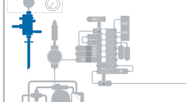
Nozzles are typically short, with a smaller diameter than the main process line from which they branch. They often house a probe, which in its simplest form is a metal, glass or ceramic proboscis that protrudes into the process fluid and withdraws a continuous flow of liquid or gas for analysis.
When determining where to position the nozzle in a pipeline or vessel, select a location where the process fluid has thoroughly mixed, so your sample accurately reflects process conditions. If possible, install an inline static mixer in the process line. If that isn’t an option, locate the tap downstream from a point of induced turbulence such as a pump discharge, flow orifice or piping elbow. The turbulence will help mix the process fluid before sampling.
Placing a sampling tap immediately after a source of turbulence isn’t good practice. The turbulence will cause pressure fluctuations and eddy currents — either of which may affect the analytical measurements.
Gas Sampling
You are better served by placing the tap at least two pipe diameters downstream of the last flow disturbance. The U.S. Environmental Protection Agency (EPA) recommends this practice. It permits two locations for manual stack gas sampling:
- At least eight stack or duct diameters downstream and two diameters upstream of any flow disturbance; or
- At least two stack or duct diameters downstream and a half diameter upstream from any flow disturbance.
The EPA considers the first location to be ideal. If the first rule cannot be met, EPA guidelines require additional sampling points to guard against the possibility of stratification.
Fluid Sampling
For pipeline sampling, locate your tap at least two pipe diameters downstream of the last flow disturbance--anywhere it doesn’t interfere with a flow-metering element. However, if the process fluid is a liquid that’s close to its bubble point, it’s wise to be more conservative. To avoid getting bubbles in your sample, locate the tap where there are at least five pipe diameters of clear straight pipe upstream and two diameters downstream.
Vapor Sampling
When the stream being sampled is a vapor at or near its dew point temperature, the tap location becomes more critical. Some condensation may occur at pressure points near flow disturbances; you don’t want your gas sample to contain liquid condensate. To minimize this potential, one European standard (ISO 10715 1997, 13) for measuring natural gas requires the sampling tap to be at least 20 pipe diameters downstream of the last flow disturbance; the relevant American standard (API MPMS 14.1 2006, 15) requires at least five pipe diameters. If the pipe contains another probe, such as a thermowell, the sampling probe should be located at least five thermowell diameters away from the thermowell.
Even greater separation is necessary for isokinetic sampling, which calls for the velocity in the probe to match that in the process line. For example, for saturated steam, the relevant American standard (ASTM D1066) recommends the sampling tap be at least 35 pipe diameters downstream and four pipe diameters upstream of a flow disturbance. Because this separation may be difficult to achieve, ASTM suggests that noncompliant locations maintain a 9:1 ratio of upstream to downstream distances.
Constructing a Nozzle
As you move into the design stage, you’ll notice that nozzle design, including orientation, highly depends upon the needs of the probe. Nozzle, and therefore probe, location and orientation can influence how particles within a process stream affect analysis. The correct nozzle and probe placement can minimize the potential for particles to enter the probe where they may contaminate the sample or collect and eventually block the probe.
The simplest way to construct a nozzle is to weld a female threaded boss to a pipeline and drill it through. First, weld a reinforcing plate to the pipeline, unless its wall is adequately thick. Next, select a boss size to accommodate the threaded probe or valve being used. Another approach is to weld a male threaded pipe nipple onto the line.
Of course, neither of these simple methods will satisfy a process piping specification that prohibits threaded joints at the process envelope. Facing these constraints, you can weld a valve onto the nipple or use a flanged pipe nozzle instead.
Tapping a Gas Stream
Whenever possible, choose a horizontal pipe for sampling process gas. The horizontal orientation allows the nozzle to be vertical. It’s also easier to find a long, straight run. Locate the nozzle on top of the line so any dirt or liquid falls back into the process pipe. If the process gas is clean and dry, you could locate a gas nozzle on the side of a horizontal pipe. However, avoid such a horizontal probe orientation for dirty samples because the gas flow in the probe may not be turbulent; solid particles could fall out and block the probe.
The same concern for blockage applies to a horizontal nozzle on a vertical gas pipeline. Inclined nozzles allow any entrained liquids or solids to fall back into the process. This feature works well for liquid removal but may not for solids, which may stick in the probe.
For vertical stacks, the nozzle should be horizontal or slightly inclined and much larger — sized to accommodate special probes. Here, nozzle location is based on the gas temperature: not too hot (so material costs are reasonable) but above the acid dew point temperature (so sulfuric acid doesn’t condense in the probe). For stack gas monitoring, the optimum gas temperature at the nozzle is a little more than 600°C (1,112°F) to ensure complete combustion.
When sampling from a process vapor flow that may contain droplets of condensate, such as a saturated steam system, the preferred tap location is a long, downward-flowing process pipe. However, always check the line pressure. A down line often connects to the suction side of a process pump and may be running at low pressure. A low-pressure source is good for a gas sample that will be vented to flare but not for one you want to return to the process via a fast loop. With a fast loop, you probably want to sample from the process pump discharge and return the gas to the suction side.
Tapping a Liquid Stream
A vertical pipeline flowing upward often is the best location for a liquid sampling nozzle because you can be sure the pipe is full. For this setup, opt for a horizontal nozzle as it allows a shorter probe that’s less likely to vibrate. A horizontal nozzle is fine for a liquid sample because the flow in the probe is sure to be turbulent, precluding sedimentation of solids in the probe.
The head of liquid in the piping above the tap will provide some extra pressure, which can ensure the process liquid at the tap is above its bubble point. The extra pressure also helps in transporting the sample. Avoid sampling a liquid from a vertical process pipe flowing downward — there’s no guarantee the line is full.
Sampling a liquid stream from a horizontal line is risky because the process pipe may not be full, resulting in a two-phase sample. If the process pipe turns upward after the horizontal run, you can be sure the line is full; if it turns downward, the horizontal section might house a static layer of gas trapped above the flowing layer of liquid.
Conventional wisdom says liquid taps always should be on the side of a horizontal process line; this is good advice when sampling without a probe. Sampling from a nozzle on the side of the line reduces the risk of extracting entrained vapor at the top of the pipe or sludge at the bottom.
In practice, it’s usually better to use a probe to reach into the center of the line. When using a probe, orientation is less important. Usually, a vertical nozzle on top of the line is preferred because it allows heavy solids to fall back into the process pipe. Generally, the nozzle shouldn’t be in the bottom of a horizontal pipe as solids will fall into it and increase the difficulty of sample conditioning. If you must use an existing bottom nozzle, install a probe that reaches into the center one-third of the pipe diameter.
Before Finalizing Tap Location
Before settling upon your final tap location, remember that your choice of probe will determine the orientation and diameter of the nozzle and its end fittings. Once you select a probe, revisit your chosen location to check the physical space available for installation and maintenance work. Verify there is enough clearance for fabricating the nozzle, maintaining the process isolation valve and withdrawing the probe. Also consider accessibility and lighting. A simple tap and pipe probe might require only a small platform and ladder, but a field station will need a full platform and lighting.
For more in-depth, personalized training assistance covering nozzle placement and sampling system design, contact your local Swagelok sales and service center.
Related Articles
Sampling Systems: 8 Common Process Analyzer Accuracy Challenges
Sampling systems expert and veteran industry instructor Tony Waters offers plant managers and design engineers tested ways to identify and resolve 8 common challenges for process analyzer accuracy.
5 Common Process Analyzer System Revelations over 50 Years of Training
Sampling systems can be one of the most challenging systems within your plant to both design and operate. Industry veteran and industrial training instructor, Tony Waters, shares his trainees’ top revelations over the past 50 years.
10 Tips to Improve Sampling Systems
Managing an analytical instrumentation operation is no small feat. Receiving consistent results can be a struggle for even the most seasoned engineers. Luckily, there are several simple tips your team can use to improve your sampling system.