The following languages are fully supported on our offering of international sites, including detailed product information and e-commerce functionality.
The principal aim of this document is to explore and highlight factors that most
directly impact the design, operation, and maintenance of industrial grade gas
distribution systems.
We examine how and why GDSs often represent a rich opportunity for operational
improvement. For facilities implementing new systems, “getting it right the first
time” is an effort that demands specialized knowledge and experience to optimize returns on investment. For facilities operating legacy systems, performance deficiencies frequently push the associated costs and risks of unaltered operation to unmanageable proportions.
To better frame the challenges commonly associated with dependable gas distribution, this white paper will focus on the concerns of lab, site, and
reliability managers responsible for ensuring the delivery of gas to a diverse range of applications without unplanned interruption.
The paper also will cover topics of importance to design and engineering managers charged with the design and specification of systems critical to
the productivity of engineering teams. Additionally, we will address the concerns of analytical instrumentation and operations managers entrusted
with safeguarding operational goals such as throughput, yield, and profitability.
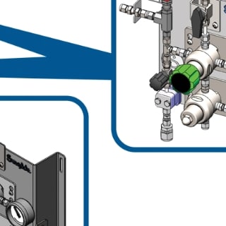
Swagelok engineers build standardized, configurable gas delivery systems to help protect system operators, increase
process uptime, and improve process accuracy and repeatability.
An Introduction to Gas Distribution Systems
What Are Gas Distribution Systems?
Gas distribution systems are interconnected assortments of specialized components—including regulators, hoses, tubes, fittings,
manifolds, and valves—that deliver gas from one or more high-pressure sources to designated points-of-use.
Where Are They Used?
Facilities that regularly use substantial quantities of industrial gas manage its
access from points-of-use using GDSs. Examples of facilities that commonly
employ GDSs include:
Onsite laboratories (e.g. sample verification)
Industrial operations (e.g. analyzer shelters)
Research facilities (e.g. commercial R&D, government, university facilities)
Chemical and gas companies (e.g. petroleum, packaging)
Medical facilities
Why Are They Used?
Facilities that use GDSs can recognize substantial value from these systems in four categories of performance:
How Are They Used?
In addition to the straightforward function of offering discrete points of access to a managed gas supply, the importance of a GDS lies in its support of critical operational functions including the capability to:
Safely convey reactive, toxic, and corrosive gases without hazardous leakage
Deliver gas to points-of-use at a specified pressure over a range of flow rates
Prevent unscheduled interruptions in critical gas supply
Handle high-cost, high-purity gases without contamination or loss
Overcoming Gas Distribution Challenges
Legacy Systems vs. New Systems
When designing the proper operation and maintenance of a
gas distribution system, it is useful to compare challenges
encountered when supporting a legacy GDS—perhaps one
installed prior to the tenure of the team currently operating
and supporting it—versus the demands of new installations.
While similarities exist between the two categories, the
differences can necessitate changes to priority and emphasis in
addressing performance and maintenance issues.
Legacy Systems
Engineers, managers, and technicians responsible for the operation and upkeep of a legacy
GDS are frequently confronted with obstacles arising primarily from its origin and design. In
many cases, the system was provided by a gas supplier at no cost to the customer. While
convenient, these systems may not be optimized for long-term performance based on
specific application needs. Challenges may arise due to:
A one-size-fits-all approach
Limited component selection options
Provided fittings’ susceptibility to wear during recurring maintenance
Material selection that meets minimum regulatory and performance requirements
Limited optimization and troubleshooting support
Without accurate documentation, even legacy systems with well-considered specifications
can present support and operational teams with challenges. Older designs in particular
tend to be inadequately labeled and less intuitive than their modern counterparts. Without
appropriate diagramming, it can be difficult to be certain that even routine maintenance or
repair will not leave the system in a state of impaired performance or even total
dysfunction.
These problems can be compounded when system function has been extended beyond its
original scope with the addition of newer components—often from vendors other than
those used in the initial design. The cumulative effect of these concerns can leave engineers
and managers with the persistent sense that they’ve inherited someone else’s
unmanageable problems. As a consequence, even leak-detection and repair efforts can end
up sidelined or deprioritized due to uncertainty of outcome or anticipated cost.
New Systems
Having explored some of the challenges associated with operating legacy distribution systems, let’s examine performance demands
related to the design of a new system. Understanding these requirements—which apply both to the remediation of legacy issues and the
proper specification of new systems—will help establish how reliability and performance can best be brought to both.
For each of the four categories in which a well-designed GDS is expected to perform (safety, resource savings, uptime, and cost), that
performance can be better attained by efforts applied in three principal areas of enhancement: Topical Education, Proper Component
Selection and Professional Consultation.
Regardless of combustibility or flammability, any gas that escapes a
distribution system represents a potential safety risk. Even inert gases like
nitrogen can pose an asphyxiation hazard because atmospheric oxygen
levels can be displaced to a hazardous degree within enclosed spaces. Toxic
and reactive gases represent an even greater threat when leaked.
Fittings and Fire Prevention
Fire becomes a very serious danger wherever the
three ingredients necessary for combustion are
present in the same location: fuel, heat, and oxygen
(as shown in the “fire triangle” diagram). While
removal of any one of the three ingredients will prevent combustion, care must always be taken in gas distribution
with regards to potential fires. For example, undetected concentrations of hydrogen or oxygen from leaky fittings
can produce dangerously combustible conditions.
Wherever possible, fire awareness and training programs should be made
available to system designers, managers, and users. Regulations and best
practices related to the specific gases being distributed should always be
thoroughly examined and incorporated into policies and guidelines—along with
regular audits of their practice—to ensure the proper treatment of hazardous
substances. Individuals responsible for distribution system design should be
educated in the proper handling of all potentially harmful gases and should notate
design documents to indicate where and why safety features have been
incorporated into the design of the system.
By choosing well-engineered fittings that are more resistant to wear, the likelihood
of leakage can be notably reduced thereby lowering risks commonly associated with
distributing both reactive and inert gases. Choosing pressure regulators that are of
correct size and material composition for intended applications can likewise address
risks associated with overpressure conditions. Careful selection of these components
will not only be instrumental in safeguarding the safety and health of personnel, but it
can also reduce possible exposure to secondary risks: regulatory penalties and/or
negative publicity arising from system malfunction. Proper component selection also
contributes substantially to the performance and longevity of the system.
To thoroughly address safety concerns, professionals specializing in the potential
hazards associated with gas distribution should be consulted throughout design and implementation of the system. When dealing with
legacy distribution systems, in particular, specialists who are also capable of performing thorough leak detection should be engaged to
identify, categorize, and prioritize any likely dangers.
Time and Resources Savings
Precise, predictable, and reliable control over pressure throughout the system is a
primary means by which a well-designed GDS can contribute to the efficient use of a
facility’s resources. Mismatched pressure management components often lead to
poor system efficiency, increased need for troubleshooting, and negative impact to
quality or process output.
Behavior of System Components
A functional understanding of how various regulators interact to maintain pressure
throughout a GDS is vital to the proper design of the system. Although GDSs are commonly regarded as little more than collections of
valves with a few tubes to connect them to gas cylinders, the truth is far more complex and occasionally the subject of drastic
misunderstanding. For example, consider a phenomenon known as “supply pressure effect” (SPE).
As a pressurized gas cylinder expels its contents into a pressure-regulated distribution system, the pressure at the inlet drops as well. If
asked what the anticipated effect on pressure would be at the outlet, a typical response would suggest a corresponding drop in pressure at
that end of the system.
However, with SPE, the opposite occurs: as pressure at the inlet drops in response to
the depletion of the cylinder, the pressure instead rises at the outlet—a
counterintuitive result that often surprises people. Understandably, without a working
knowledge of SPE, the phenomenon can lead to confusion, even giving rise to the
belief that one or more of the system’s components has malfunctioned.
Troubleshooting is performed needlessly, and time is wasted.
To counteract SPE, several approaches can be taken, one of which is to simply manually
reset outlet pressure to desired levels in response to the effect. However, this approach
is inefficient and unwieldy in all but low-use applications.
One alternative to manual reset is the selection and installation of a “balanced poppet”
pressure regulator—one in which offsetting outlet pressure is used to counteract the
effect of dropping inlet pressure on a specially designed poppet assembly.
The other alternative is the incorporation of a second pressure regulator—either inline with the first or with both regulators contained in a
single integrated housing—to counteract SPE in the upstream regulator with an inversion of its primary effect by the downstream
regulator. This configuration is known as two-stage regulation.
Given the example of SPE, it’s easy to see why a working understanding of pressure regulator function is critical to proper GDS design.
Similar considerations are important to understanding the role of other components as well, such as back-pressure regulators—which,
when improperly integrated, can unintentionally impair or negate the function of other regulators in the system. Training programs
provided by industry leaders and educators can be effectively used to properly acquaint engineers and managers with design and function
considerations of this nature.
In addition to understanding the behavior of pressure regulators, it is also important to become familiar with their performance
characteristics. These are expressed in the form of graphs known as “flow curves.”
Flow Curves
Regulators control pressure. Downstream valves control flow—the volumetric measure of gas flowing through the regulator every second.
Each regulator has a corresponding flow curve that describes how effectively the regulator can maintain outlet pressure (the Y-axis in the
graph) in response to flow changes (the X-axis in the graph) that occur when valves are opened and closed. As seen in the diagram, the
relationship between flow and maintainable outlet pressure is inversely proportional: when flow increases, outlet pressure decreases and
vice-versa.
A careful examination of the graph reveals that there is a broad X-axis range where changes in flow result in relatively gentle (or
“flattened”) changes to maintainable pressure. This region represents the “ideal operating range” of the regulator, the system conditions
under which it can most efficiently control outlet pressure. The slope of this region is referred to as the “droop,” with a perfectly flat,
horizontal line being a hypothetical, but realistically unattainable, ideal.
There are also ranges at both extremes of the curve where even small changes in flow result in drastic changes to maintainable pressure.
At the far left-hand side of the graph, the steep region of the curve is known as the “seat-load drop” or “lockup,” a range of very low flow in
which the downstream valve is very nearly closed. At the far right-hand side of the graph, the steep region of the curve is known as “choked
flow,” a range of high flow in which the downstream valve is in or near a fully opened position. These are flow domains in which the
regulator is unable to exert reliable control over pressure.
By selecting the appropriate flow curve for a given “set pressure” (the pressure at which a regulator begins operation), and by applying
adjustments for temperature, inlet pressure, and the specific gravity of the gas in use, anticipated application flow demands can be used to
select regulators that will reliably maintain desired pressure.
Component Selection
Once desired performance characteristics are understood (i.e. flow vs. pressure), suitable pressure regulators can be selected for use in any
of the four categories of customizable gas-panel subsystems that typically comprise a well-performing GDS.
source inlet
automatic changeover
primary gas pressure control
point-of-use
Source Inlet
The source inlet is the “beginning” of the system, a point
at which high-pressure gas sources, often in the form of
pressurized cylinders, feed into the GDS. These can be
configured—along with appropriate auxiliary components
like filters, hoses/tubes, etc.—for one or more input
sources, ranging in form factor from single panels to
larger manifold that accommodate multiple cylinders.
Automatic Changeover
The automatic changeover system seamlessly switches from one gas source to another to ensure an uninterrupted supply. This is
accomplished through staggered set points of two pressure regulators, allowing the system to continue to operate as the primary gas
source is changed.
Primary Gas Pressure Control
The primary gas pressure control resides in the “middle” of the system and provides initial pressure reduction to the high-pressure gases
fed from the source inlet. This can take the form of single or multi-stage pressure regulator(s) that control the supply gas to downstream
system segments.
Point-of-Use Panel
The point-of-use panel represents the “end of the line,” the critical final stage at which pressure-regulated gas is supplied to the application
supported by the GDS. Point-of-use panels typically, at a minimum, furnish operators with a pressure regulator, a gauge, and an isolation
valve to precisely adjust pressure to match the needs of the application.
Guidance supplied by professionals specializing in the development of gas distribution systems can quickly bring confidence to the
process of correctly understanding and selecting pressure regulators. By getting pressure regulation “right the first time,” unnecessary
expenditure of resources—including testing material, design resources, and personnel hours—is minimized.
Professional consultation can also be useful in correctly customizing and/or accessorizing selected components. For example, source inlets
may require specialized connective components—often using special material composition—when handling high-pressure or hazardous
gases (such as oxygen).
Increased Uptime
One practical area in which the value of a GDS can be easily understood is its contribution
to uptime. With the integration of high-performance, high-quality, low-maintenance
components into system design, the supply of pressure-regulated gas to critical
applications—such as analyzers—can be achieved with virtually no unplanned interruption.
Training system designers and managers in the function of pressure regulators allows for
an intuitive grasp of component functionality that allows a seamless continuity of gas flow
even when swapping out sources. Additionally, by properly educating system designers
and managers in a breadth of component characteristics, they will be equipped to
incorporate components that require less frequent offline maintenance.
One component that handily contributes to uninterrupted
operation is a changeover, particularly an automatic
changeover. A changeover is a specialized inlet panel that
allows two gas sources to be connected to a distribution
system such that when one cylinder exhausts its contents, the
other is immediately engaged to provide continuity of service.
An automatic changeover performs this source substitution
without the need for manual intervention.
By consulting with professionals specializing in the design and
operation of gas distribution systems, a clear picture of issues
impacting uptime can be developed. Working with
experienced and well-trained specialists to identify and classify
components according to their uptime contribution allows
designers to better focus on features that reduce the need for
frequent maintenance.
Reduced Costs
Importantly, a well-designed GDS can reduce operational costs. As previously noted, the selection of high-reliability components that use
materials appropriate to the application can greatly reduce the frequency of routine maintenance and inspection as well as reduce the
likely need for unplanned maintenance. Also, using proper filtration in conjunction with precise pressure controls can help ensure that
application output is unaffected by contamination or deviation from process specifications.
Proper training can help managers and system designers better
align their efforts with facets of system operation that impact
costs. Understanding how issues such as inline filtration and
material science potentially affect system performance and
downstream quality can help avoid unplanned expenses. Design
choices, such as modular panels that include minimal threaded
connections, may reduce potential leak points, which can affect
overall costs. Training in the various aspects of material science
related to gas distribution will likewise help avoid expenses arising
from improper material use.
Components selected for inclusion in the distribution system
should always be selected with attention to proven durability and
meticulously matched to anticipated performance characteristics and material requirements. Flow curves, for example, change
dramatically for the worse when a pressure regulator is used with inlet pressures for which it is not designed. Likewise, certain gases
should only be used with components of suitable chemical composition and that precisely align with expected temperatures and source
pressures.
Conclusion
When it comes to gas distribution systems, every good solution is a custom solution. Whether designing a new GDS or remediating a legacy
system, careful attention must be paid to the infrastructure and the operational challenges unique to the application.
Understanding the nuances of various GDS configurations and components can help organizations improve safety, conserve resources,
enhance uptime, and, ultimately, reduce costs.
Even with the highest quality components in hand, the flow demand of any given application coupled with the interplay between inlet
sources, pressure regulators of various types, and application points-of-use outlets requires a thorough knowledge of GDS function prior to
designing a solution that performs well and sustainably.
Swagelok is committed to promoting that knowledge not only within our own skilled advisory teams but to our customers and throughout
our industry.